
GPS clock
After my finishing my bachelor project I had some spare LOCOSYS LS20031 GPS modules bought at Sparkfun. The modules proofed to perform poorly at positioning, for my application, but they do provide a good time base.
I reckoned, would I be awed by my peers when I would build a clock showing the time received by a GPS receiver?
Display and power considerations
I choose to build the clock using the ATmega162 PCB that I've also had laying around. (check my main page)
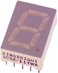
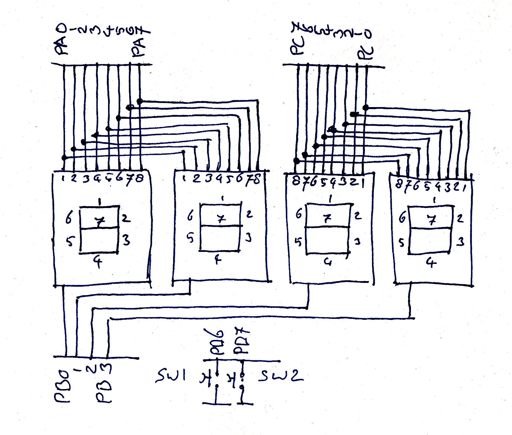
The clock face is made up of 4, 7 segment displays of the SA52-11EWA type. The first two displays have common cathodes and are connected through 330 Ohm resistors to port A pin 0 trough 6. So on each pin two led cathodes are connected. The same goes for the last two displays and port C pin 0 through 6. The common anodes of display 1 through 4 are connected to port B pin 0 trough 3. So each pin sources the current for the 7 LED's of the display.
When I turn on a single led and measure the current, my multimeter reads 7.5 mA. When I read the ATmega162 data sheet, I find that a single pin can source or drain 40 mA. The whole IC can source or drain 200 mA. For the pins of port A and C there does not seem to be a problem. Each pin has to drain 15 mA which is well within 40 mA. The four port A pins are a different story. When 7 segments are turned on a pin has to source 52.5 mA. That is 12.5 mA to much. It is not as it should be but I think the sturdy AVR will manage. Also the ATmega162 has quite a large body thus being better at heath dissipation. This schematic shows the connections.
RS232
At the start of the building I knew I had to communicate with the LS20031, using the RS323 protocol at 3.3V LVTTL. What I didn't knew was at which speed. I wanted to use a clock source for the ATmega162 that would suffice for all speeds. Luckily I can stand on the shoulders of people, who designed the RS232 protocol and gave thought to this.
I've made an Excel sheet to calculate the different UBRR values for the respective Baud rates, showing the Error percentage. To get the RS232 communication running you need to have an error less than 1 percent. Try out some different stock available clock speeds and see what Baud rates are possible.
The following table shows the errors for a clock source of 7372800 Hz (column 2 and 3) and 16000000 Hz (column 4 and 5). The first clock matches perfectly with the RS232 hardware. (except for Baud rate 250000) The second clock, running at the MEGA162 maximum, generates a lot of unusable baud rates.
| Baud | UBRR | Error % 1 | UBRR | Error % 2 |
| 2400 | 191 | 0,000 | 415 | 0,160 |
| 4800 | 95 | 0,000 | 207 | 0,160 |
| 9600 | 47 | 0,000 | 103 | 0,160 |
| 14400 | 31 | 0,000 | 68 | 0,644 |
| 19200 | 23 | 0,000 | 51 | 0,160 |
| 28800 | 15 | 0,000 | 33 | 2,124 |
| 38400 | 11 | 0,000 | 25 | 0,160 |
| 57600 | 7 | 0,000 | 16 | 2,124 |
| 76800 | 5 | 0,000 | 12 | 0,160 |
| 115200 | 3 | 0,000 | 7 | 8,507 |
| 230400 | 1 | 0,000 | 3 | 8,507 |
| 250000 | 0 | 84,320 | 3 | 0,000 |
I'll use a 7372800 Hz crystal.
Electronic interfacing
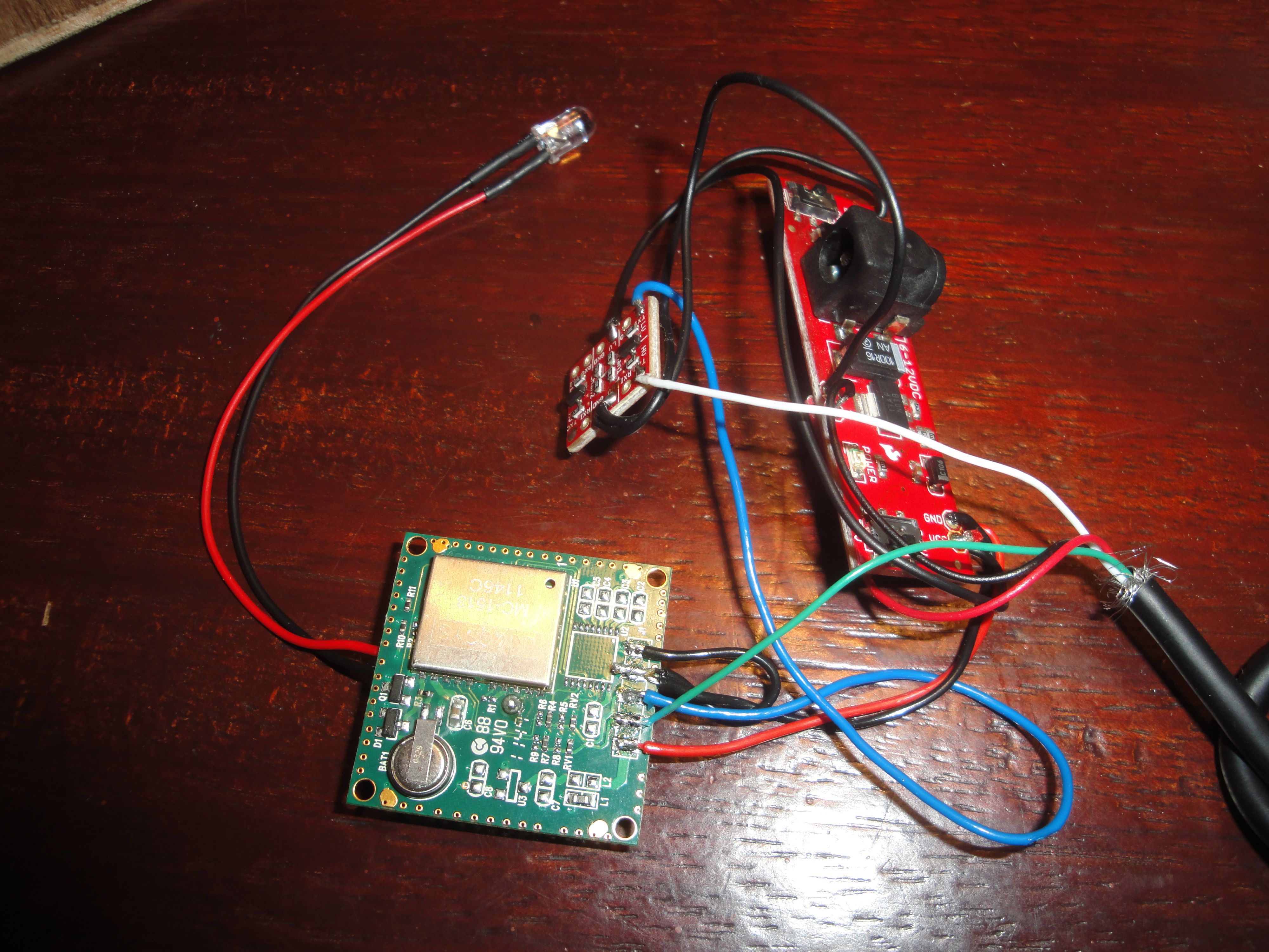
I've decided to keep the GPS module out of the clock casing. When it's put in it's casing connected by a cable it's much easier to place the receiver away from the clock at a position where it has clear reception. This image shows the innards of the receiver casing.
On the GPS module a SMD led is mounted witch will flash every second when a GPS fix is established. I like to see this signal when the module is in a box, so I replaced it with a normal LED.
The cable delivers 5V power on wire red and ground on wire black. The GPS module (the green one, and it is not easy being green!) operates at 3.3V so I used a voltage regulator board (the large rectangular one) from Spark Fun to power the module and the Spark Fun level changer.(the small square one)
The blue wire connects the 3.3V output from the GPS module to the level changer. Here the 3.3V signal is transformed to a 5V signal which is what the MEGA162 needs as RS232 input. To get this done the level changer needs to be fed with 5V from the cable. The white wire leaves the level changer with the 5V signal.
It is also necessary the configure the GPS module. This is done trough the green wire. I don't use the level changer to get the signal down to 3.3V but use a different trick. After the GPS module is programmed with the right configuration it is not necessary to write to it again. The programming of the GPS module will be done aside the clock, using a Arduino. When programming the output of the GPS module also has to be connected to the Arduino.
I,ve used the following setup.
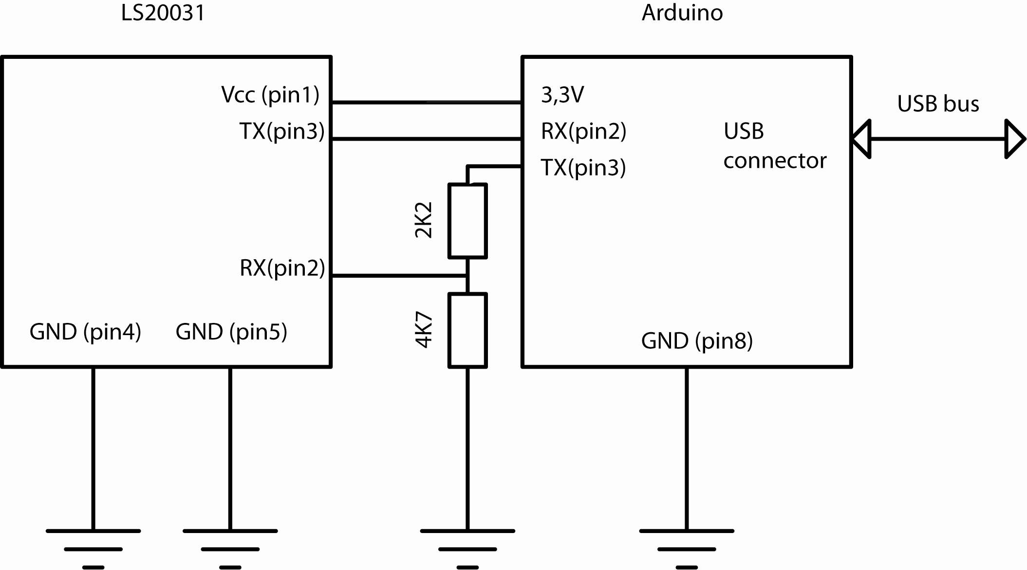
The micro controller has been taken out of the Arduino's socket. Now I can easily program and read the LS20031. My favorite terminal app for Windows is RealTerm. I've used the MiniGPS tool for the actual programming. Make sure to use version 1.4 when using a Windows version above XP.
Open MiniGPS, connect to the right com port, set the communication speed at 14400 baud, enable ZDA to 1, set output rate to once per second and save the config.

Code
When the hardware is assembled, it is time to swing some code. I figured out that the GPS sentence starting with $GPZDA contains time and date information. This information is available regardless of the fix state of the GPS receiver. In my country the GPS time is one hour behind winter time and two hours behind summer time. I formulated two requirements:
- The clock must have a button to increase the hours.
- The clock must have a button to show the date.
While testing the hardware, some constraints became apparent. The GPS module outputs a block of data with the size of about 600 characters during 0,2 seconds, every second. The micro controller does not have enough memory to buffer the whole block of data. While reading the data there isn't much time to do anything else. It became clear that processing of the data should be done after receiving it. Being a proper engineer nowadays, I started modelling pseudo code and came up with something like this:
| Declarations: |
|
| Main: |
|
| Character received: |
|
| Timer interrupt: |
|
When I turn this into C code, I get the following:
(For proper outlining, open the project in AVR Studio 6.0)
// GPS clock
//
// This software runs on a ATMEGA162. It receives GPS messages and displays the time and date
// on 4 7 segment displays. Two buttons are connected. After pressing button A, the date is shown.
// After pressing button B, the hours will be set one hour forward.
//
// This is free software, enjoy!
//
// Count0, feb 2013

#include <avr/io.h>
#include <avr/interrupt.h>

#define COMPARING	0	// Recieving states
#define READING		1
#define DONE		2
#define SHOW_TIME	0	// Showing states
#define SHOW_DAY	1
#define SHOW_MONTH	2
#define SHOW_YEAR	3

volatile char state_recieving;				// Machine state while recieving
volatile char state_showing = SHOW_TIME;	// Machine state while showing

volatile char valueA = 0;	// These contain the actual values shown on the displays
volatile char valueB = 0;
volatile char valueC = 0;
volatile char valueD = 0;

volatile char imageA;	// These contain the bitmaps corresponding with the values
volatile char imageB;
volatile char imageC;
volatile char imageD;

volatile char message[100];			// A string to receive the sentence from the GPS
static char compare[] = "$GPZDA,";  // This is the start of the sentence we want to capture
volatile char messageCount;			// The number of chars read during successfully reading
volatile int index1;				// Indexes for the strings
volatile int index2;

volatile char keyBpressed = 0;	// 0 = not pressed
volatile char udr_data;			// Will contain UDR value
volatile char hourOffset = 1;	// This value will be added to the time the GPS delivers

void toDecimal(int decimal) // Express a value from 0 to 9999 as 4 chars (for debugging)
{
	if (decimal < 10000)
	{
		valueA = decimal / 1000;
		decimal = decimal - valueA * 1000;
		valueB = decimal / 100;
		decimal = decimal - valueB * 100;
		valueC = decimal / 10;
		decimal = decimal - valueC * 10;
		valueD = decimal;
	}
	else
	{
		valueA = 14;
		valueB = 14;
		valueC = 14;
		valueD = 14;
	}
}

ISR(TIMER1_COMPA_vect) // Timer tick, we are now some time after we received the GPS char
{
	TCCR1B &= ~((1 << CS12));	// Stop timer clock
	char hours;

	if (state_showing == SHOW_TIME)
	{
		if (keyBpressed)	// Increse the offset if key B was pressed
		{
			hourOffset++;
			if (hourOffset == 24) hourOffset = 0;
		}

		valueD = message[3] - 48;	// Set minutes,
		valueC = message[2] - 48;	// 48 is ASCII for number 0

		valueA = 0;
		hours = message[1] + ((message[0] -48) * 10) - 48 + hourOffset; // Recalculate to real hours + offset

		if (hours > 23) hours = hours -24;	// Express hours as two chars
		while (hours > 9)
		{
		valueA++;
		hours = hours - 10;
		}
		valueB = hours;

		message[48]	= 13; // CR, terminate the message for sending
		message[49]	= 10; // LF
		message[50] = 0;  // Null
		index1 = 0;

		while(message[index1]) // Output message for debug purposes
		{
			while(!(UCSR0A & (1<<UDRE0))){}	//Wait untill the transmitter is ready
			UDR0 = message[index1];
			index1++;
		}
	}

	if (state_showing == SHOW_YEAR)
	{
		valueA = message[17] - 48;
		valueB = message[18] - 48;
		valueC = message[19] - 48;
		valueD = message[20] - 48;
		state_showing = SHOW_TIME;
	}

	if (state_showing == SHOW_MONTH)
	{
		valueA = 0x10;
		valueB = 0x10;
		valueC = message[14] - 48;
		valueD = message[15] - 48;
		state_showing = SHOW_YEAR;
	}

	if (state_showing == SHOW_DAY)
	{
		valueA = 0x10;
		valueB = 0x10;
		valueC = message[11] - 48;
		valueD = message[12] - 48;
		state_showing = SHOW_MONTH;
	}

	index1 = 0;
	index2 = 0;
	state_recieving = COMPARING;

	keyBpressed	= 0;
}

ISR(USART0_RXC_vect) // Serial char received
{
	udr_data = UDR0;	// Fetch the received byte

	if (state_recieving == READING) // We had the right prefix
	{
		if (messageCount++ < 50)	message[index1++] = udr_data; // Add the char to the message string.
		else
		{
			state_recieving = DONE;	// Stop receiving
			messageCount = 0;
		}
	}

	if (state_recieving == COMPARING) // We are checking for the right prefix ($GPRMC,)
	{
		if (udr_data == compare[index2]) // Char match?
			{
				index2++;
				if (udr_data == ',' ) state_recieving = READING; // Last char yes? then start reading the rest
			}
		else index2 = 0; // We had a wrong char, compare from start again.
	}

	TCNT1 = 0;					// Reset the clock and set it running.
	TCCR1B |= ((1 << CS12));	// Precaler 256.
}

char toImage(char decimal)	// Deliver the bitmap to the corresponding value
{
	char x = 255;
	if (decimal == 0x00) x = 0b11000000; // 0
	if (decimal == 0x01) x = 0b11111001; // 1
	if (decimal == 0x02) x = 0b10100100; // 2
	if (decimal == 0x03) x = 0b10110000; // 3
	if (decimal == 0x04) x = 0b10011001; // 4
	if (decimal == 0x05) x = 0b10010010; // 5
	if (decimal == 0x06) x = 0b10000010; // 6
	if (decimal == 0x07) x = 0b11111000; // 7
	if (decimal == 0x08) x = 0b10000000; // 8
	if (decimal == 0x09) x = 0b10010000; // 9
	if (decimal == 0x0A) x = 0b10001000; // A
	if (decimal == 0x0B) x = 0b10000011; // B
	if (decimal == 0x0C) x = 0b11000110; // C
	if (decimal == 0x0D) x = 0b10100001; // D
	if (decimal == 0x0E) x = 0b10000110; // E
	if (decimal == 0x0F) x = 0b10001110; // F
	if (decimal == 0x10) x = 0b11111111; // blank

	return x;
}

void init_USART()
{
	UBRR0L = 31;		//  14400 baud @ 7.372.800 Hz
	UBRR0H = 0;

	UCSR0B = (1<<RXEN0 | 1<<TXEN0);		// Enable RX and TX
	UCSR0C = (1<<URSEL0)|(3<<UCSZ00);	// 8 data, 1 stop bit

	UCSR0B |= (1 << RXCIE0); // Enable receive interrupt
}

void init_timer(void)
{
	// P is Period between ticks:
	// P = OCR * prescaler * (1/clock)
	// So:
	// OCR = P / (precaler * (1/clock))
	// (Clock in hz, P in secs)

	TCCR1B |= (1 << WGM12);		// Configure timer 1 for CTC mode
	TCCR1B |= ((1 << CS12));	// Precaler 256
	OCR1A   = 2880;				// Set CTC compare value to 0.1 Hz at 7.372.800 Hz AVR clock
	TIMSK |= (1 << OCIE1A);		// Enable CTC interrupt
}

int main (void)
{
	DDRA = 255;			// Segments for display 1 & 2
	DDRB = 0b00001111;	// Common cathodes for displays 1 through 4
	DDRC = 255;			// Segments for display 1 & 2
	DDRD = 0b00000100;	// Configure port D as input except pin 3, for debugging
	PORTD = 0b11000000; // Configure pin 6 and 7 with pull up resistors active (button A, button B)

	index1 = 0;
	index2 = 0;

	init_timer();
	init_USART();
	sei();			//  Enable global interrupts

	while (1)	// Multiplex the displays and check for key presses while no interrupt is taken care of
	{
		imageA = toImage(valueA);
		imageC = toImage(valueC);
		PORTA = imageA;
		PORTC = imageC;
		PORTB = 0b00000101;	// Light display A and C

		imageB = toImage(valueB);
		imageD = toImage(valueD);
		PORTA = imageB;
		PORTC = imageD;
		PORTB = 0b00001010;	// Light display B and D

		if (!(PIND & 1 << 6)) state_showing = SHOW_DAY; // Check if Pin is pulled low
		if (!(PIND & 1 << 7)) keyBpressed = 1;
	}
}
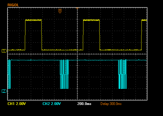
Everything works and everyone's happy. A small bug remained. The display shows a slight flicker every second. When the data block is received, the micro processor is so busy that the main routine doesn't get enough time to multiplex the display. This bug was solved by declaring it a feature.
If someone removes this feature, I am happy to post the code.
I've gratefully used the CodeColorizer tool to do C2HTML. It is the best that I have found. When someone knows a better one, please mail me.