
Nixie clock MK II
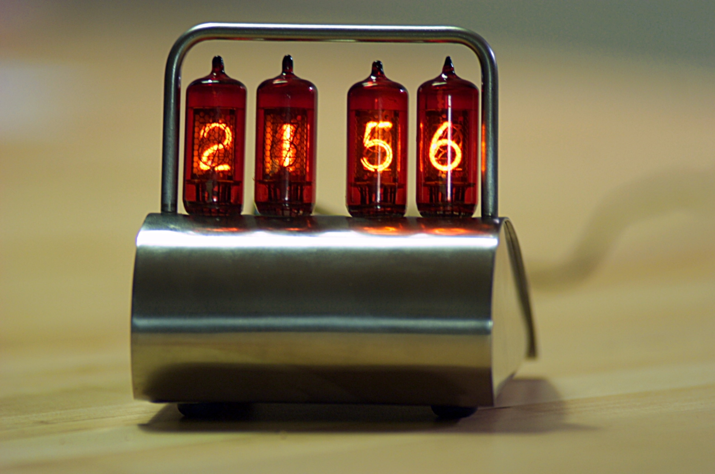
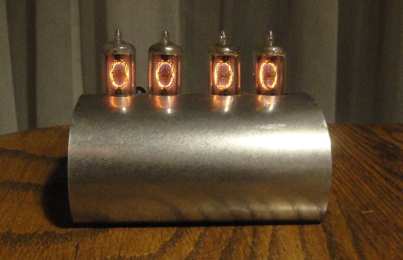
This project was quite a family collaboration. Some years ago my dad gave me an ancient PCB with ten CD82 Nixie tubes, about 40 to 60 years old. I've decided, with the help of my dear aunt Ruud to build him a clock as a birthday present. The clock was realized and looked splendid but performed poorly. Ruud profided a very nice casing though. My dad decided to equip the casing with closed bottom and sides and to give it a roller bar, to protect the tubes.
For the original I've used an ATMega8 as a controller and time base. The clock went stray for several minutes a day. Also the 180V DC power wasn't operating satisfactory. (actually, it blew up several times)
For nostalgic reasons I keep a picture of the MK I.
Quiting is always an option to consider. We choose otherwise.
Board
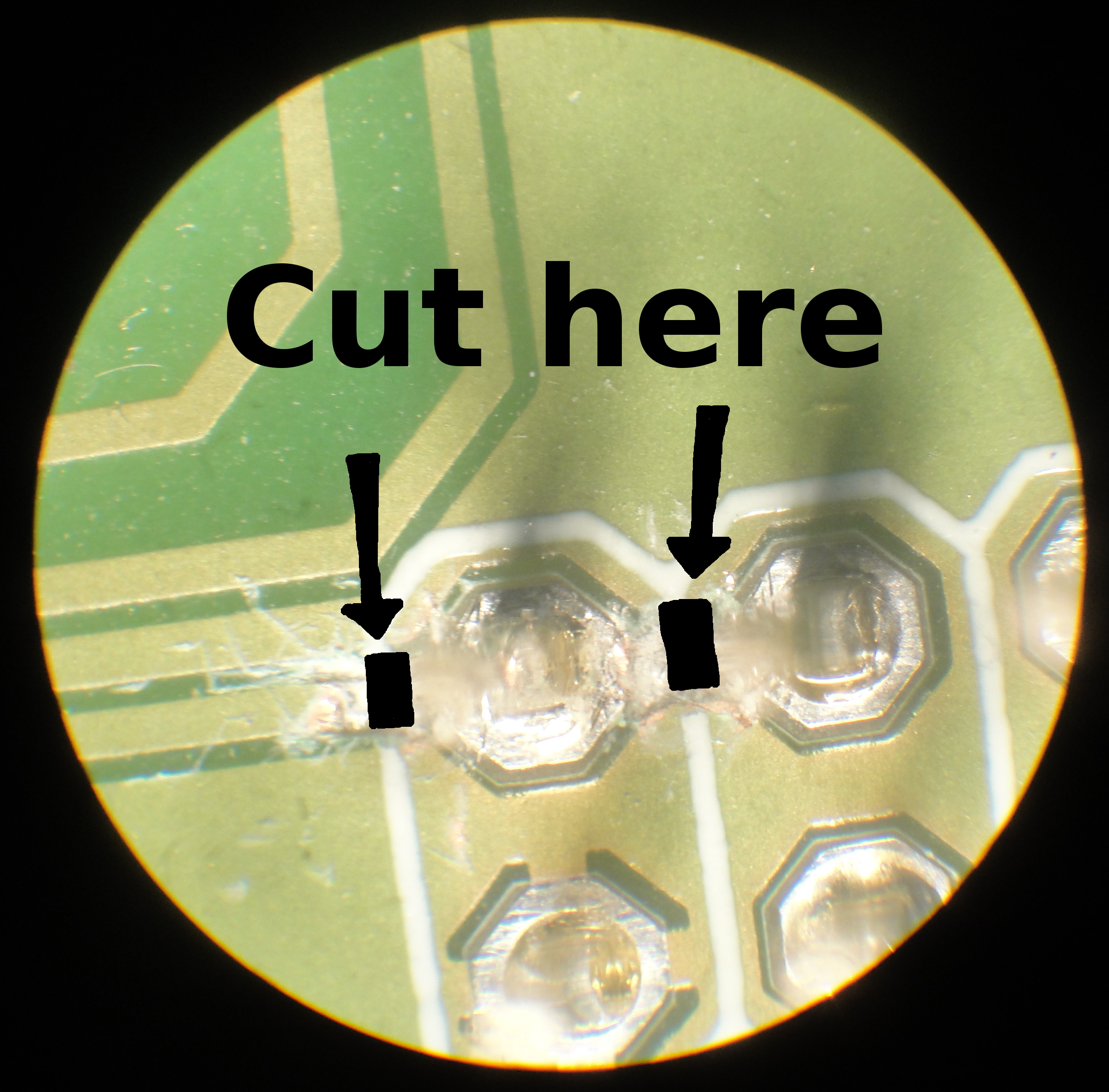
Of course I've designed my own PCB for the clock, and made a mistake. When you get the PCB produced, you have to fix the problem by cutting two signal lines and applying a piece of wire. The problem is located at the top side of the PCB at the AVR ISP interface. On the board the SCK and RTS pin have a short circuit. Cut the signal as shown in the picture at the right, and connect SCK to pin 11 (SCLK) on the DS1305 RTC. I've put the repairing wire on the lower side.
Please be welcome to download the Eagle CAD PCB files here.
Discretes
For the accuracy problem, I've choose to use the well known DS1305 serial Real Time Clock. I've did not encounter any real problems. Well, it took some time to figure out that the SPI interface can could not handle the speed of bit banging I've started out with. And despite of the excellent examples found on the Internet, it took me some time to configure it.
A nice feature of the DS1305 is that it can run on auxiliary power. I've equipped the IC with a 0.1F super cap, which keeps the clock running for at least 72 hours, when the power is off.
The controller is a ATtiny2313 with a 20MHz clock. Because the 2313 does not have enough pins to directly control the Nixie drivers, I've used two 74HCT595 shift registers to set a 16 bit, bit pattern just using 4 lines. Please look at the schematic, and an incomplete bill of materials.
Tubes
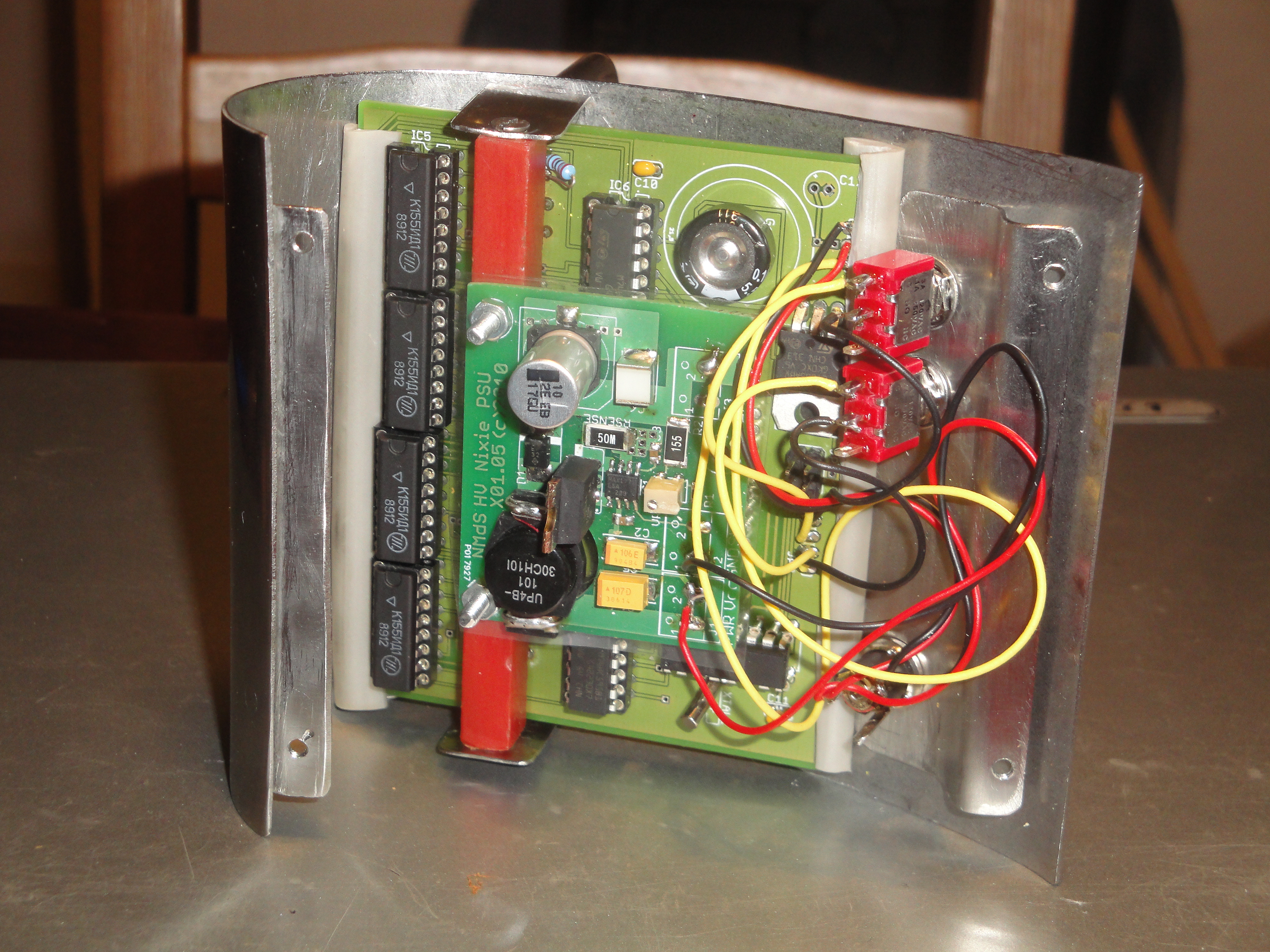
To fix the 180V power supply problem, I've choose to step upon someone else his shoulders. Nick de Smith provided us with an excellent Nixie HV Switching PSU. I've gratefully downloaded his CAD files and got the PCB's manufactured. What is especially helpful is the list particular components to use, and their part numbers to order them at Digikey or Farnell.
Thank you Nick!
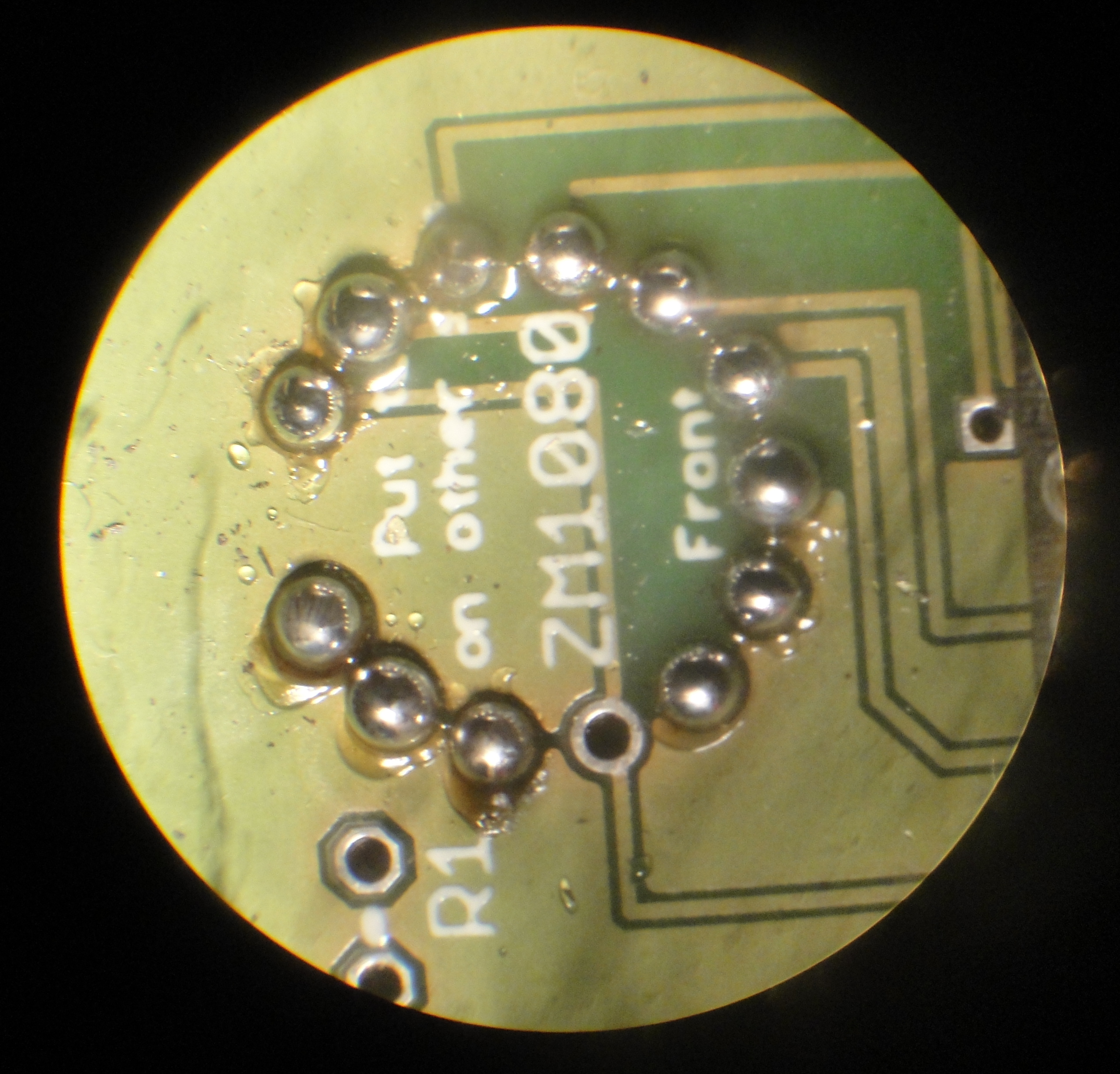
The picture on the right shows how I've soldered the tube on the board. For each wire I applied very litte solder. Then I cut off the wires as short as possible, to apply more solder until a little tin bead was created with no wire sticking out. Electrons on a sharp edge will creep to the point of the edge witch will become increasingly negative, resulting in a electron spray. I don't know how strong this effect is at 170V but I've had enough stray electrons in my live.
Software
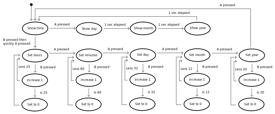
When you click the UML icon on the right of this text, a state diagram describing the clock behavior will pop up. I love state diagrams to develop micro controller software, for micro controllers are mostly state machines. (just like people) This state diagram is quite close to a user manual.
To access the RTC I've used a bit banging routine. The ATtiny2313 has hardware on board to perform SPI communication but I did not get it to work in a reasonable amount of time.
While coding with the use of the more and less marvelous AVR-Studio IDE, Windows broke down again. Years ago I tried to install an AVR development environment on Ubuntu but got stuck. But not today anymore. Just an:
apt-get install gcc build-essential
apt-get install gcc-avr gdb-avr binutils-avr avr-libc avrdude
did the job.
The building process depends on a makefile. Cd into the code directory and type:
make
sudo make install (when using a AVRISPII programmer)
I did not figure out the debugging environment yet, but the building of the machine code is so much faster that I only use AVR-Studio for infrequent emulation sessions. The C code. looks like this:
/*
Count0's nixie clock MKII

This code drives a nixie clock build of 4 ZM1080 nixie tubes, a DS1305 RTC,
an Atmel ATtiny2313, HCT595N shift registers, 74141N nixie drivers and some
passive components. The power for the tubes is derrived from a high voltage
switching PSU kindly taken from:
<http://www.desmith.net/NMdS/Electronics/NixiePSU.html>

Thank you Nick!

This code should have come with Eagle CAD board and schematic files.
If not, or if looking for more documentation, visit Count0's site:
<http://count00.home.xs4all.nl/>

This program is free software: you can redistribute it and/or modify
it under the terms of the GNU General Public License as published by
the Free Software Foundation, either version 3 of the License, or
(at your option) any later version.

This program is distributed in the hope that it will be useful,
but WITHOUT ANY WARRANTY; without even the implied warranty of
MERCHANTABILITY or FITNESS FOR A PARTICULAR PURPOSE.  See the
GNU General Public License for more details.

You should have received a copy of the GNU General Public License
along with this program.  If not, see <http://www.gnu.org/licenses/>.
*/

#define F_CPU 20000000
#include <avr/interrupt.h>
#include <util/delay.h>

// SPI control to read/write the real time clock IC
#define	SPI_MOSI	PB5
#define	SPI_MISO	PB6
#define	SPI_SCK		PB7
#define	SPI_DDR		DDRB
#define	SPI_SS		PB4
#define SPI_PORT	PORTB
#define SPI_PIN		PINB

// Button control
#define BUTTONS		PIND
#define BUTTONA		PD2
#define BUTTONB		PD3

// Shift register control to output codes for the nixie tubes
#define SHIFT_DATA		PB0
#define SHIFT_CLOCK		PD6
#define SHIFT_NOT_RESET	PD5
#define SHIFT_TO_OUT	PD4

#define DEBOUNCE		30	// Time after button pressed until new button pressed is read

// The different states the clock can hold
#define STATE_SHOWING_TIME      0
#define STATE_SETTING_MINUTES	1
#define STATE_SETTING_HOURS     2
#define STATE_SETTING_DAY       3
#define STATE_SETTING_MONTH     4
#define STATE_SETTING_YEAR      5
#define STATE_SHOWING_DATE      6

// Control codes for the real time clock IC
#define GET_HOURS       0x02
#define SET_HOURS       0x82
#define GET_MINUTES     0x01
#define SET_MINUTES     0x81
#define GET_DAY         0x04
#define SET_DAY         0x84
#define GET_MONTH       0x05
#define SET_MONTH       0x85
#define GET_YEAR        0x06
#define SET_YEAR        0x86
#define SET_CONTROL     0x8F
#define SET_CHARGE      0x91

volatile unsigned char  state =	STATE_SHOWING_TIME;
volatile unsigned int   animation_timer;
volatile unsigned int   get_time_timer;

volatile unsigned char buttonApressed	= 0; // If not 0, button has been pressed.
volatile unsigned char buttonBpressed	= 0; // Should be reset to read next button press.
volatile unsigned char buttonspressed   = 0; // Both buttons pressed
volatile unsigned char buttonAdebounce	= 0; // While not 0, ignore next button presses,
volatile unsigned char buttonBdebounce	= 0; // to ignore button bouncing.

volatile unsigned char tube1; // Actual code to display on the tube
volatile unsigned char tube2;
volatile unsigned char tube3;
volatile unsigned char tube4;

volatile unsigned char tube1_flashing = 0; // When not 0 it's flashing
volatile unsigned char tube2_flashing = 0;
volatile unsigned char tube3_flashing = 0;
volatile unsigned char tube4_flashing = 0;

volatile unsigned char flash = 1; // While flashing, if tube is on or off.
volatile int flash_timer= 0;	  // Timer to toggle flashing tubes on or off.

volatile unsigned char hr_one       = 0; // Time data
volatile unsigned char hr_ten       = 0;
volatile unsigned char min_one      = 0;
volatile unsigned char min_ten      = 0;
volatile unsigned char day_one      = 0;
volatile unsigned char day_ten      = 0;
volatile unsigned char month_one    = 0;
volatile unsigned char month_ten    = 0;
volatile unsigned char year_one     = 0;
volatile unsigned char year_ten     = 0;

// Send and recieve an SPI byte trough software bit banging.
unsigned char SPI_bang(unsigned char data)
{
	unsigned char bit = 0;

	for(bit = 0; bit < 8; bit++)          // Loop through 8 bits
	{
		if(data & 0x80) SPI_PORT |= (1<<SPI_MOSI);	// If bit(7) of "data" is high
		else SPI_PORT &= ~(1<<SPI_MOSI);			// if bit(7) of "data" is low
		SPI_PORT |= (1<<SPI_SCK);					// Serial Clock Rising Edge
		_delay_us(200);
		data <<= 1;									// Shift "data" to the left by one bit
		if(SPI_PIN & (1<<SPI_MISO)) data |= (1 << 0);	// If bit of slave data is high
		else data &= ~(1 << 0);						// if bit of slave data is low
		SPI_PORT &= ~(1<<SPI_SCK);					// Serial Clock Falling Edge
		_delay_us(200);
	}
	return data;                      // Returns shifted data in value
}

// Get a value from the RTC
unsigned char SPI_read(unsigned char command)
{
        unsigned char result;

        cli();

        SPI_PORT |= (1<<SPI_SS);	// Select slave
        result = SPI_bang(command);        // Fetch hours
        result = SPI_bang(0);
        SPI_PORT &= ~(1<<SPI_SS);	// Deselect slave

        _delay_us(200);

        sei();

        return result;
}

// Send a value to the RTC
void SPI_write(unsigned char command, unsigned char data)
{
        cli();

        SPI_PORT |= (1<<SPI_SS);    // Select slave
        SPI_bang(command);          // Fetch hours
        SPI_bang(data);
        SPI_PORT &= ~(1<<SPI_SS);	// Deselect slave

        _delay_us(200);

        sei();
}

// Set timer TC1 to raise an interrupt every 1/100 th second,
// with system clock running at 16 MHz
void TC1_Init(void)
{
	OCR1A = 0x094C;
	TCCR1B |= (1<<WGM12) | (1<<CS11) | (1<<CS10);	// Set prescaler 1024 and countmode to CTC
	TIMSK |= (1 << OCIE1A); 						// Enable CTC interrupt
}

// Set all shifter bits to 0.
void ShifterReset(void)
{
	PORTD &= ~(1<<SHIFT_NOT_RESET);
	_delay_us(50);
	PORTD |= (1<<SHIFT_NOT_RESET);
}

// Put shifter data on output pins.
void ShifterOutput(void)
{
	PORTD |= (1<<SHIFT_TO_OUT);
	_delay_us(50);
	PORTD &= ~(1<<SHIFT_TO_OUT);
}

// Set a pattern of bits on the shifter data registers.
void ShifterSet(unsigned char a, unsigned char b, unsigned char c, unsigned char d)
{
	unsigned char bit = 0;
	unsigned int data = 0;	// 16 bit

	data = a + (b*16) + (c*256) + (d*4096);

	for(bit = 0; bit < 16; bit++)          // Loop through 8 bits
	{
		if(data & 0x8000) PORTB |= (1<<SHIFT_DATA);	// If bit(7) of "data" is high
		else PORTB &= ~(1<<SHIFT_DATA);				// if bit(7) of "data" is low
		data <<= 1;

		PORTD |= (1<<SHIFT_CLOCK);
		_delay_us(50);
		PORTD &= ~(1<<SHIFT_CLOCK);
	}
}

// This routine is triggered by hardware timer TC1 every 1/100 second.
ISR(TIMER1_COMPA_vect)
{
    cli(); // Globally disable interrupts. We wont want to be disturbed.

	animation_timer++;
	get_time_timer++;
    flash_timer++;

	// Decrease debounce counters
	if (buttonAdebounce) buttonAdebounce--;
	if (buttonBdebounce) buttonBdebounce--;

	// Set button pressed?
    if ((!(BUTTONS & (1<<BUTTONA))) & (!buttonAdebounce))
    {
        buttonAdebounce = DEBOUNCE;
        buttonApressed = 1;
    }

    if ((!(BUTTONS & (1<<BUTTONB))) & (!buttonBdebounce))
    {
        buttonBdebounce = DEBOUNCE;
        buttonBpressed = 1;
    }

    if (buttonApressed & buttonBpressed) buttonspressed = 1; else buttonspressed = 0;

	if (flash_timer > 50)   // Toggle flash every 500 ms
	{
		flash_timer = 0;
		if (flash == 1) flash = 0; else flash = 1;
	}

	// Fetch the time from the RTC every 30 ms
	if ((get_time_timer > 30) & (state == STATE_SHOWING_TIME))
	{
        unsigned char minute, hour, day, month, year;

        get_time_timer = 0;

        hour   = SPI_read(GET_HOURS);
        minute = SPI_read(GET_MINUTES);
        day    = SPI_read(GET_DAY);
        month  = SPI_read(GET_MONTH);
        year   = SPI_read(GET_YEAR);

        min_one     = (minute & 0b00001111);
        min_ten     = (minute & 0b01110000)/16;
        hr_one      = (hour   & 0b00001111);
        hr_ten      = (hour   & 0b00110000)/16;
        day_one     = (day    & 0b00001111);
        day_ten     = (day    & 0b00110000)/16;
        month_one   = (month  & 0b00001111);
        month_ten   = (month  & 0b00110000)/16;
        year_one    = (year   & 0b00001111);
        year_ten    = (year   & 0b11110000)/16;
	}
	sei();
}

// Reset button presses after reacting to them.
void flush_buttons(void)
{
    buttonApressed = 0;
    buttonBpressed = 0;
}

// Program entry point.
int main(void)
{
	// Set the pins for RTC communication.
	SPI_DDR = 0;
	SPI_PORT = 0;
	SPI_PORT &= ~(1<<SPI_SS);	// Deselect slave
	SPI_DDR |= (1<<SPI_MOSI)|(1<<SPI_SCK)|(1<<SPI_SS);

	// Set the pins to programm the shift registers.
	PORTD = 0;
	PORTD |= (1<<SHIFT_NOT_RESET);
	DDRD |= (1<<SHIFT_CLOCK)|(1<<SHIFT_NOT_RESET)|(1<<SHIFT_TO_OUT);
	DDRB |= (1<<SHIFT_DATA);

	// Enable internal pull up resistors on the button pins.
	PORTD |= (1<<BUTTONA)|(1<<BUTTONB);


	_delay_ms(1000);
	ShifterReset(); // All tubes to blank.

	SPI_write(SET_CONTROL,0);			// Enable RTC
	SPI_write(SET_CHARGE,0b10100101);   // Make use of the supercap for backup power

	TC1_Init();

	sei();		// Enable global interrupt

	while(1)
	{
        switch(state)
		{
            case STATE_SHOWING_TIME:

                tube1 = hr_ten;
                tube2 = hr_one;
                tube3 = min_ten;
                tube4 = min_one;

                if (buttonspressed)
                {
                    state = STATE_SETTING_HOURS;
                    tube1_flashing = 1;
                    tube2_flashing = 1;
                    _delay_ms(1000);
                    flush_buttons();
                }

                if (buttonApressed)
                {
                    animation_timer = 0;
                    state = STATE_SHOWING_DATE;
                    flush_buttons();
                }
                break;

            case STATE_SHOWING_DATE:

                flush_buttons();

                if (animation_timer == 2)
                {
                    tube1 = day_ten;
                    tube2 = day_one;
                    tube3 = 10;
                    tube4 = 10;
                }

                if (animation_timer == 200)
                {
                    tube3 = month_ten;
                    tube4 = month_one;
                }

                if (animation_timer == 400)
                {
                    tube1 = 2;
                    tube2 = 0;
                    tube3 = year_ten;
                    tube4 = year_one;
                }
                if (animation_timer > 600)
                {
                    state = STATE_SHOWING_TIME;
                    tube1_flashing = 0;
                    tube2_flashing = 0;
                    tube3_flashing = 0;
                    tube4_flashing = 0;
                }
                break;

            case STATE_SETTING_HOURS:

                if(buttonBpressed)
                {
                    hr_one++;

                    if (hr_one == 10)
                    {
                        hr_one = 0;
                        hr_ten++;
                    }

                    if ((hr_ten == 2) & (hr_one == 4))
                    {
                        hr_ten = 0;
                        hr_one = 0;
                    }
                }

                if(buttonApressed)
                {
                    SPI_write(SET_HOURS, (hr_one + (hr_ten *16)));

                    tube1_flashing = 0;
                    tube2_flashing = 0;
                    tube3_flashing = 1;
                    tube4_flashing = 1;
                    state = STATE_SETTING_MINUTES;
                    flush_buttons();
                }

                flush_buttons();

                tube1 = hr_ten;
                tube2 = hr_one;
                tube3 = min_ten;
                tube4 = min_one;
                break;

            case STATE_SETTING_MINUTES:

                if(buttonBpressed)
                {
                    min_one++;
                    if (min_one == 10)
                    {
                        min_one = 0;
                        min_ten++;
                    }
                    if (min_ten == 6) min_ten = 0;
                }

                if(buttonApressed)
                {
                    SPI_write(SET_MINUTES, (min_ten * 16) + min_one);

                    tube1_flashing = 1;
                    tube2_flashing = 1;
                    tube3_flashing = 0;
                    tube4_flashing = 0;
                    state = STATE_SETTING_DAY;
                    flush_buttons();
                }

                flush_buttons();

                tube1 = hr_ten;
                tube2 = hr_one;
                tube3 = min_ten;
                tube4 = min_one;
                break;

            case STATE_SETTING_DAY:

                if(buttonBpressed)
                {
                    day_one++;
                    if (day_one == 10)
                    {
                        day_one = 0;
                        day_ten++;
                    }
                    if ((day_ten == 3) & (day_one == 2))
                    {
                        day_one = 1;
                        day_ten = 0;
                    }
                }

                if(buttonApressed)
                {
                    SPI_write(SET_DAY, (day_ten * 16) + day_one);

                    tube1_flashing = 0;
                    tube2_flashing = 0;
                    tube3_flashing = 1;
                    tube4_flashing = 1;
                    state = STATE_SETTING_MONTH;
                    flush_buttons();
                }

                flush_buttons();

                tube1 = day_ten;
                tube2 = day_one;
                tube3 = month_ten;
                tube4 = month_one;
                break;

            case STATE_SETTING_MONTH:

                if(buttonBpressed)
                {
                    month_one++;
                    if (month_one == 10)
                    {
                        month_one = 0;
                        month_ten++;
                    }
                    if ((month_ten == 1) & (month_one == 3))
                    {
                        month_one = 1;
                        month_ten = 0;
                    }
                }

                if(buttonApressed)
                {
                    SPI_write(SET_MONTH, (month_ten * 16) + month_one);

                    tube1_flashing = 1;
                    tube2_flashing = 1;
                    tube3_flashing = 1;
                    tube4_flashing = 1;
                    state = STATE_SETTING_YEAR;
                    flush_buttons();
                }

                flush_buttons();

                tube1 = day_ten;
                tube2 = day_one;
                tube3 = month_ten;
                tube4 = month_one;
                break;

            case STATE_SETTING_YEAR:

                if(buttonBpressed)
                {
                    year_one++;
                    if (year_one == 10)
                    {
                        year_one = 0;
                        year_ten++;
                    }
                    if ((year_ten == 2) & (year_one == 3))
                    {
                        year_one = 0;
                        year_ten = 0;
                    }
                }

                if(buttonApressed)
                {
                    SPI_write(SET_YEAR, (year_ten * 16) + year_one);

                    tube1_flashing = 0;
                    tube2_flashing = 0;
                    tube3_flashing = 0;
                    tube4_flashing = 0;
                    state = STATE_SHOWING_TIME;
                    flush_buttons();
                }

                flush_buttons();

                tube1 = 2;
                tube2 = 0;
                tube3 = year_ten;
                tube4 = year_one;
                break;
        }

		if (tube1_flashing & flash) tube1 = 10;
		if (tube2_flashing & flash) tube2 = 10;
		if (tube3_flashing & flash) tube3 = 10;
		if (tube4_flashing & flash) tube4 = 10;

		ShifterSet(tube1,tube2,tube3,tube4);
		ShifterOutput();
	}
}